[ index | VIDEO | video synthesizers ]
paik-abe video synthesizer
The Rockefeller Foundation artist-in-residence program [at WGBH-TV in Boston] also brought Nam June Paik and filmmaker Stan Vanderbeek to broadcast television. Nam June began his year at WGBH in 1968-1969, doing a short segment for "The Medium Is the Medium". He and Shuya Abe built their first video synthesizer there and first displayed its imagery in a four-hour-long blockbuster program called "Video Commune", broadcast during the summer of 1970. The sound track was all of the Beatles' recorded music; people were invited off the streets to help contribute material (often their faces) for the synthesizer to process. Viewers at home watched four hours of dense, layered, slowly shifting, brilliantly colored images, some of which were recognizable and some not.
- Johanna Branson Gill: VIDEO: STATE OF THE ART, 1976
---
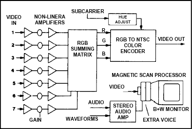
The Paik-Abe Video synthesizer was a collaboration between Nam June Paik and video engineer Shuya Abe. The basic synthesizer is a colorizer, but in keeping with Nam June Paik's method to create a "smorgasbord of video art", a scan modulator was often found adjacent to the colorizer. Combining video feedback, magnetic scan modulation, and non-linear mixing followed by colorizing, generated its novel style of imagery.

The basic Paik-Abe is a colorizer unit with seven external video inputs and corresponding gain controls. Each of the seven inputs drive various nonlinear processing amplifiers. The amplifier passes low level signals but folds over or inverts the polarity of higher level signals. High brightness components are turned into "negative" video while low brightness components can pass through without change. The output of the seven distorted amplifiers drive (depending on the version) a patch panel, a bank of switches or are "hard-wiring" to a resistive matrix. Of the seven signals, Shuya Abe believed that "Channel 6 should have the weaker signal, to maintain a sense of balance in the instrument."
The matrix adds proportions of the seven signals to the Red, Blue and Green signals that drive an RGB to NTSC color encoder. The NTSC color encoder is constructed from a printed circuit board pulled from a Sony or Shibaden Color Camera with a variety of video sync signals supplied to it from a sync processor deriving Color Burst, Subcarrier, Sync and Blanking. A large multi-turn Hue knob is present to rotate the overall hue of the colorized picture. The knob adjusts the phase of the chroma subcarrier feeding the NTSC encoder while keeping the Burst phase constant.
A common matrix configuration is to cross-wire the order of the inputs to other colors. This causes overlapping colors to add together forming new colors. An example is to tie:
Input 1 to RED,
Input 2 to Green,
Input 3 to Blue,
Input 4 to RED and GREEN (yellow),
Input 5 to RED and Blue (magenta),
Input 6 to Green and Blue (cyan), and
Input 7 to Red, Green and Blue for a monochrome mix.
The input gain controls overdrive the non-linear amps and the multiple cameras create additive color mixes of their input signals. Some of the input cameras could be pointed in a video feedback loop. Other cameras would point at a “magnetically scan processed” monitor modulated by audio signals.
The magnetic scan processing is achieved through extra deflection yokes placed on top of an existing black and white monitor yoke. The extra yoke is supplemented with additional coils wound around the neck of the picture tube, all driven by high power audio amplifiers. The deformed magnetic image is re-scanned off the face of the tube and fed into the colorizer. This forms color spaces that can be superimposed upon other synthetic image sources. The combination of signals by an external video keyer joins the colorized collage with other video backdrops, forming a rich video landscape.
—J.S. http://artscilab.org/eigenwelt/pdf/126-129.pdf
[ index | 1970 | video synthesizers ]